Groundbeds
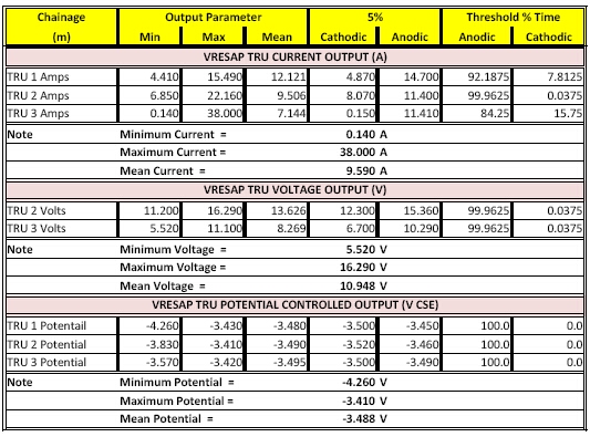
No information has been given about the performance of any of the groundbeds except the transformer-rectifier outputs under certain test conditions.
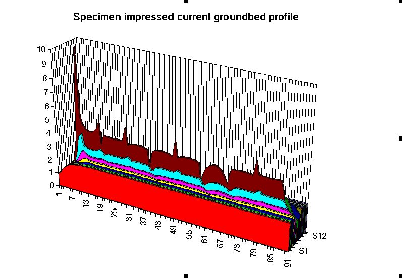
In order to determin the area of 'remote earth' it is necessary to plot a potential profile of each groundbed and it is unlikely that this has been done.
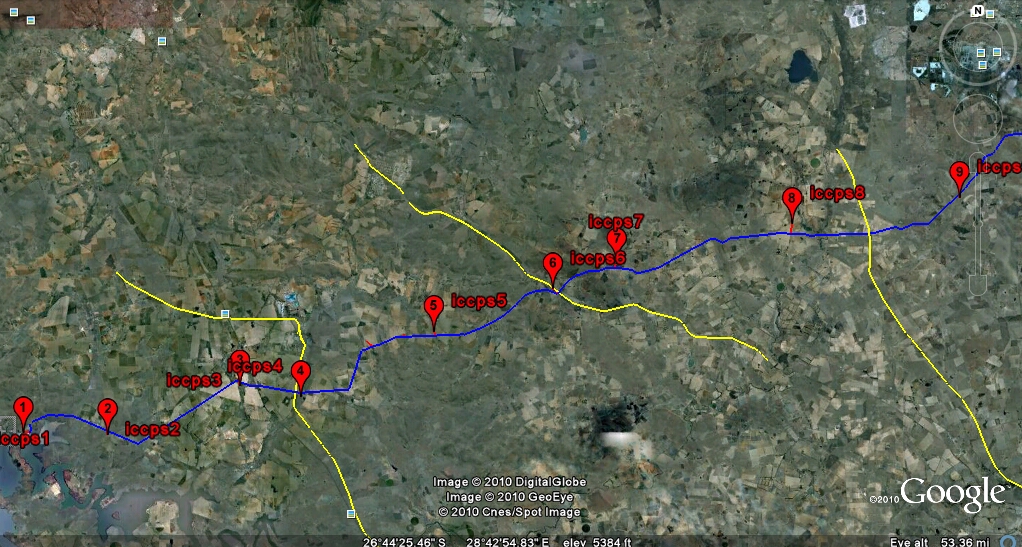
The positions of each groundbed and comments are as follows. The pictures from Google Earth are marked with likely isopotential contours to be confirmed with actual voltage measurements when these are available from the ground potential surveys.
These contours will give a realistic indication of the earth resistance between various parts of the pipeline and other metalic paths of the integrated circuit formed by all the cathodic protection in the area.
Link to iccps 1 page
Link to iccps 2 page
Link to iccps 3 page
Link to iccps 4 page
Link to iccps 5 page
Link to iccps 6 page
Link to iccps 7 page
Link to iccps 8 page
Link to iccps 9 page
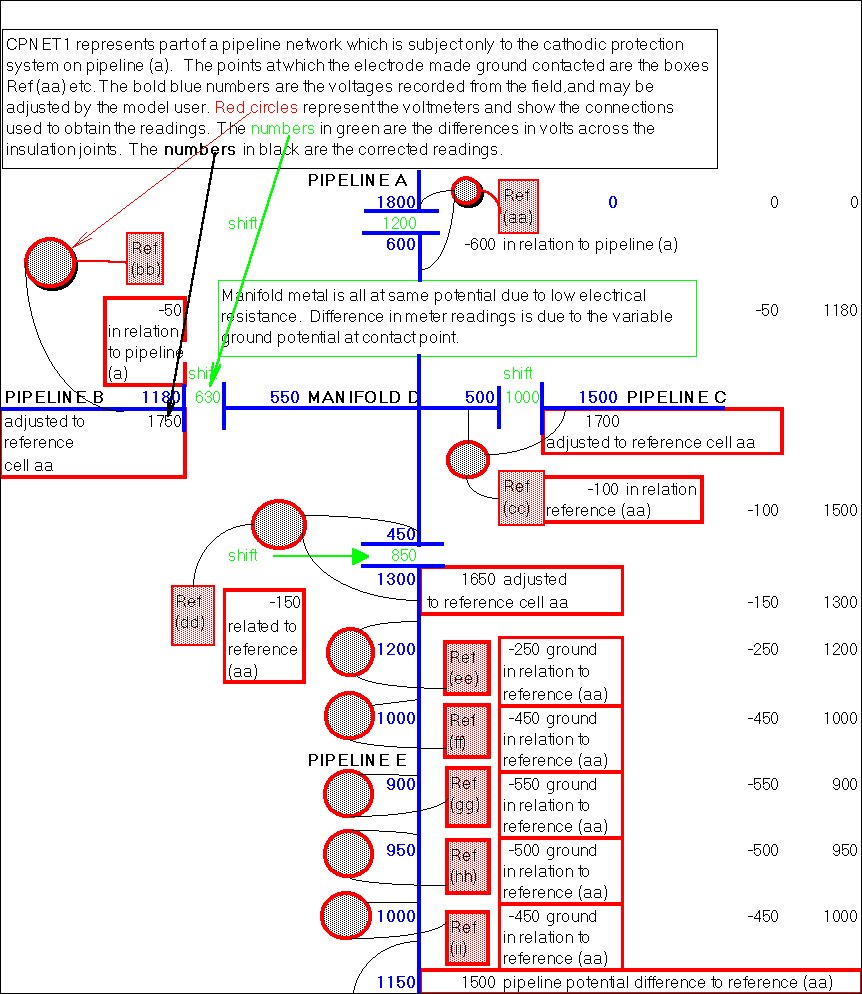
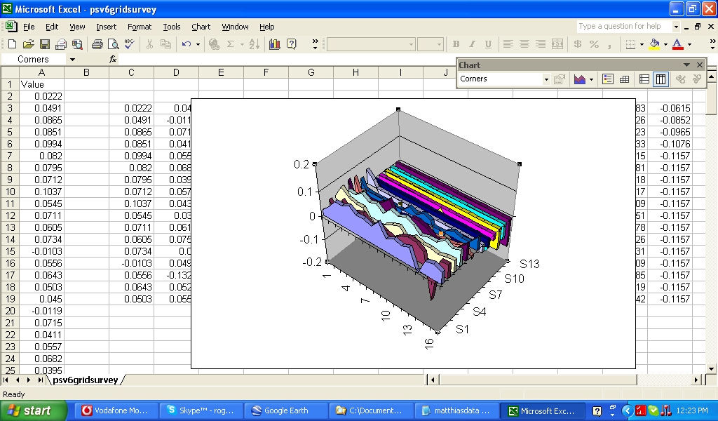
If the ground potentials have been recorded correctly it is then possible to create a map of all the ground potentials by relating all electrode potentials back to a single reference.
This will show the actual tendency for the pipeline to receive and discharge to the earth and it is in areas of discharge that corrosion will be found at coating faults.
The crucial measurement is the corrosion current at the anode of a corrosion cell and this is easily determined using the Alexander Cell.
When there is interference causing discharge from the pipeline the corrosion current in the Alexander Cell increases and the polarity stays the same. This is the case at one location we have tested already.
Genuine DCVG and CIPS will not necessarily detect coating faults in such areas as they depend on a depression in the potential profile whereas there will be an increase in the potential due to additional charges coming from the pipeline.
It is possible to recognise this condition by ground potential grid plots of the areas where interference and other problems are suspected due to indications from the CIPS and DCVG together with currents measured at all nodes in the complete system.
The complete cathodic protection system and area it ocupies should be examined as an integrated electrical circuit as suggested in the paper 'A definitive criterion for cathodic protection' presented at two international conferences in 2009.