Bulk CIPS and DCVG surveys
Close Interval Potential Surveys were conceived by Mike Foskett and Bob Greenwood of British Gas and I was part of the team that developed them in the field, combining DCVG (that I had originated earlier) and recorded Pearson Survey that has recently been renamed as Pipeline Current Mapping (PCM)
The VRESAP pipeline is a continuous steel conductor with little electrical resistance over 114KMs, and the voltages that are recorded use the pipeline as a common reference. Both types of survey record ground potentials but that potential might vary due to an assortment of causes. It is therefore necessary to record the fluctuations in this potential over the period of any CIPS survey. Cathodic Protection Network has a formal procedure relating to this.
Link to the relevant CPN Procedure
There is no description of the method of conducting a 'bulk CIPS and DCVG survey' and the data is reported in graphic format covering the whole pipeline.
VRESAP BFG KP2000 to KP15000 CP Report and VRESAP BFG Testing Report KP25-KP47 show graphs resulting from the surveys that are two sparse to be analysed and the recorded voltage data needs to be used to produce graphs that can be related to each specific area.
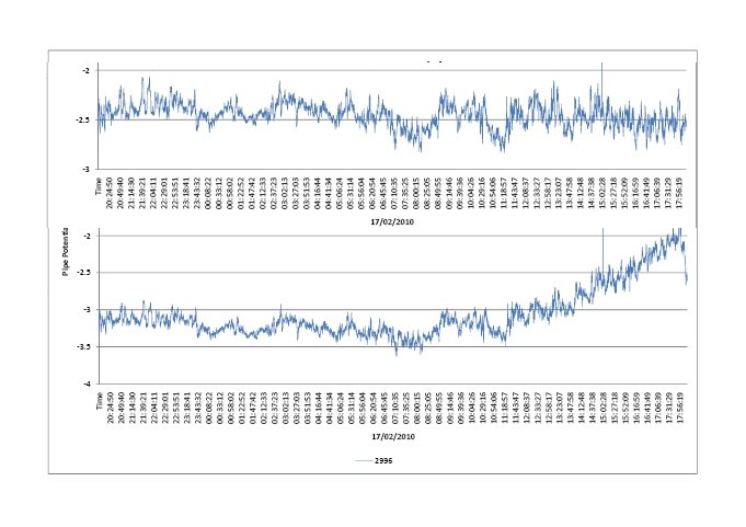
The static voltages recorded over time on the same day show that the ground potentials at each test location are the cause of the variation in the potential plotted. The pipe has so little resistance that it's potential can be safely regarded as the baseline of the graph, wherever the meter sets the zero.
By comparing the shape and magnitude of each graph over the same period it is obvious that it is the ground potential that is fluctuating and not the pipe potential.
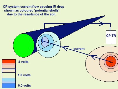
This will cause current to flow from the pipe when it's potential is higher than the ground and to the pipe when lower.
However it is the EMF of the anodic interface that determins whether corrosion takes place so this must be used to determin the criterion for protection.
CIPS voltages are useful in showing the peaks and troughs of the ground potential but must be related to a common ground reference potential. This is not as difficult as it may seem as the pipeline metal has little resistance and remote earth has none.
The resistances in the cathodic protection circuit are the 'shells of resistance' at the anode and the 'shells of resistance at the coating faults.
The resistance of the coating itself can be worked out through the manufacturers specifications and the total coating area. When conducting CIPS surveys it is good practice to include the resistance of the trailing wire and to note that this can act as an aerial picking up AC disturbances to the measurement.
It will certainly receive induced AC when working parallel to overhead power lines and 'walkie-talkie' communications create wild fluctuations.
Close Interval Potential Surveys require voltages to be logged every meter with the cathodic protection impressed current being switched on and off synchronously over the whole pipeline.
Such surveys can provide a general idea of the current distribution from all transformer-rectifiers and indicate the location of coating faults.
DCVG (as described by Dr Leeds) does not require conductive contact with the pipeline and cannot define the corrosion status. It does require the transformer-rectifier to be switched to cause the galvanometer needle to flick in the direction of the ground current flow.
Using two 'half-cells' the two surveys can be combined to locate and size coating faults with a great degree of accuracy in the right circumstances. However, it must be recognised that the digital meter used for the combined survey can only measure voltages and the 'half-cells' are only ground contact probes.