
Submarine Pipeline Failures
Roger Alexander
Corrosion Control Technologist
Analysis of the observations and data obtained from the experiments
The experiments are based on previous experiments published on Youtube and our website.
The three nails experiment shows how stray current interference causes corrosion.
Faraday, Ohms and Kirchhoff codified the behaviour of electrical energy and these are incorporated in these experiments.
Opinions are no good without evidence in the form of data and repeated observations supported by photographs and video clips.
All data must be considered. This is like a court of law or tribunal that must examine all evidence, even if it tends to disprove the opinion of the reporter.
All the materials used are in common use and all instruments available at retail in most oil producing countries. This is to allow anyone to replicate these experiments and prove the credibility of their own opinions.
Stage 1
Calculations using the data acquired during these experiments allows computer modeling to be applied. This is why we need to examine the resistance in the measuring circuit that is the first experiment using dry sand, then distilled water, then salted water. (Distilled water is highly resistant to electrical charges.)
1.
The measuring circuit resistance is important in calculating the current between the CPN half-cell and the pipe metal.
2.

This is NOT the current in the CP circuit or the current in each corrosion cell on the pipes.
3.
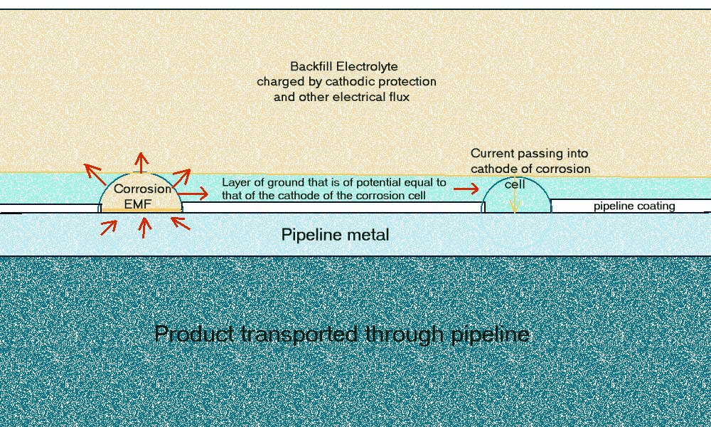
This drawing shows the corrosion current in each corrosion cell on the outer surface of the pipeline metal.
4.
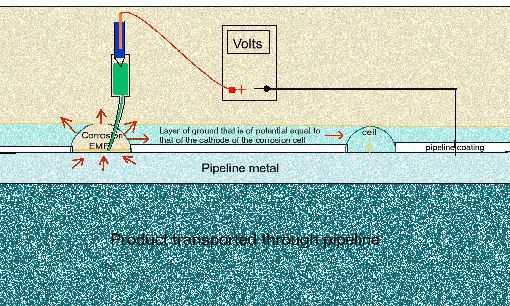
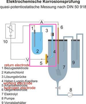
This drawing shows the way that we should make the measurement according to the scientific standard for making such measurements DIN 50819.
5.
6.

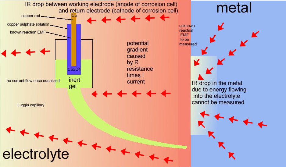
The CPN half -cell is one step towards making a correct measurement and proves that the expression 'IR drop in the soil' is a gross misunderstanding.
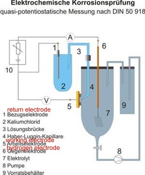
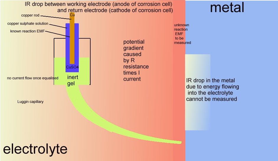
7.

This drawing explains the requirement for a Luggin capillary or similar arrangement to put the probe at the interface between the metal and the electrolyte without disturbing the value of the reaction.
8.
This is the real measuring circuit.
9.
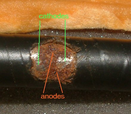
This is a corrosion cell
10.
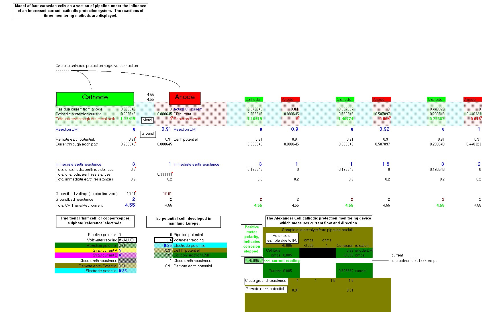
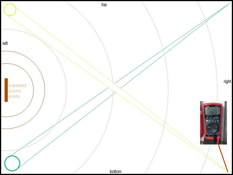
This is a computer model of a corrosion cell under the influence of an impressed current cathodic protection system. This model is part of the Cathodic Protectio Network Dynamic Project.
11.
12.
These two drawings explain the current flowing during cathodic protection measurement.
13

This is the Pourbaix Diagram in which you can see that the X axis is the pH value of the elecrolyte and this is explained in CPN teachings but not seen in others.
Stage 2
14.
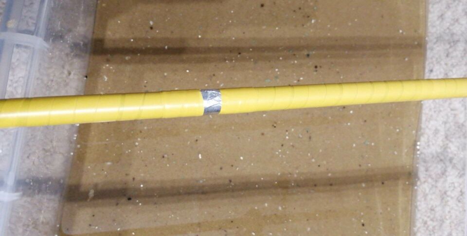
The Nord Stream Pipeline is 1 1/2" thick walls over 40" dia steel that has a very low resistance to electrical energy so it is easy for us to model the electrical circuitry using small pipes over shorter distances with very similar circuit resistances. This picture shows a replica of an aluminium bracelet anode of our experimental model.
15.
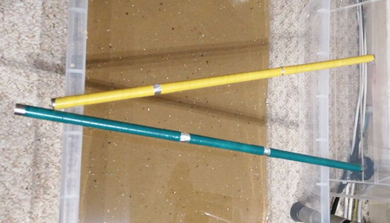
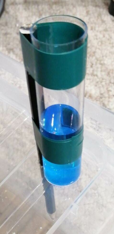
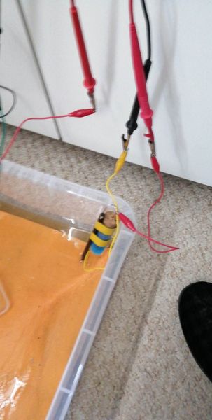
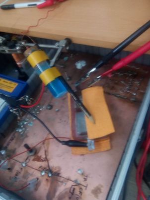
This pictures shows our two experimental pipes each with two bracelet anodes in order that we can show how interference from an impressed current CP system can cause accellerated corrosion on a pipeline protected with bracelet sacrificial anodes.
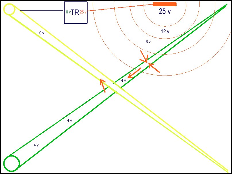
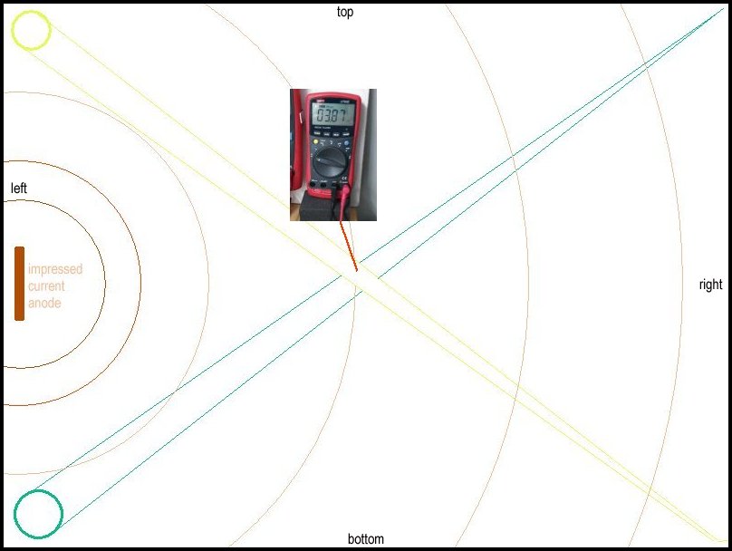
This sketch shows the condition in which we would expect stray current corrosion. The TR is causing a potential difference between the ground in different zones due to the resistance of the wet sand forming shells of resistance radiating out from the anode until it reaches equilibrium with the whole tray. When the current reaches the bracelet anode on the green pipe the energy in the electrolyte is greater than the energy created by the corrosion reaction of the aluminium and the energy passes onto the green pipe raising the pipe metal potential to 4 volts with reference to the zero on the negative terminal of the TR.The second bracelet anode on the green pipe is already discharging to the electrolyte which is remote from the CP anode. This causes the aluminium to dissolve quickly leaving the bare steel with a greater potential than the electrolyte and to dissolve. This is accelerated corrosion.
17.
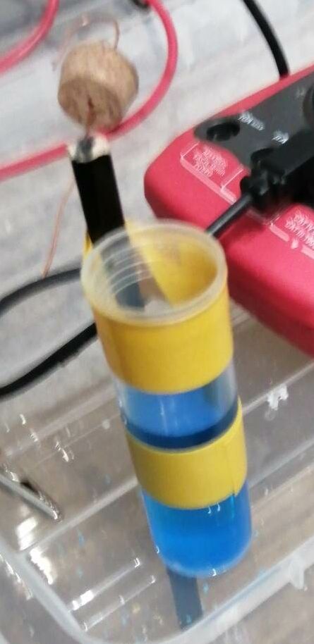
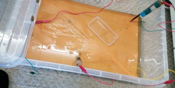
This pictures shows the yellow pipe with the two bare patches turned black and no alluminium crossing over the other pipe that has been stripped to show the two places where the impressed current has entered and left the metal.
This pictures shows the yellow pipe with the two bare patches turned black and no alluminium crossing over the other pipe that has been stripped to show the two places where the impressed current has entered and left the metal.


An accurate time and TR setting record was not kept during this first series of experimental demonstrations as caculations were not possible due to the nature of the replica bracelet sacrifcial anodes. However, the first stage was for about four hours as evidence of interference is apparent during the three nails demonstration in 2 to 3 hours.
 ..
.. ..
.. ..
.. ..
..
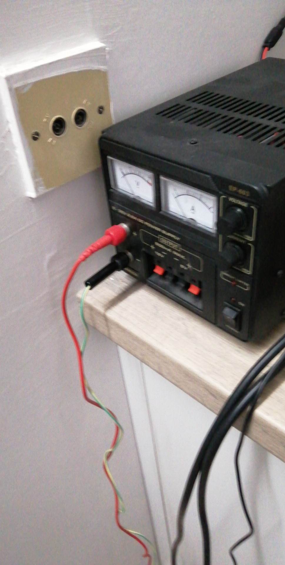
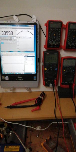
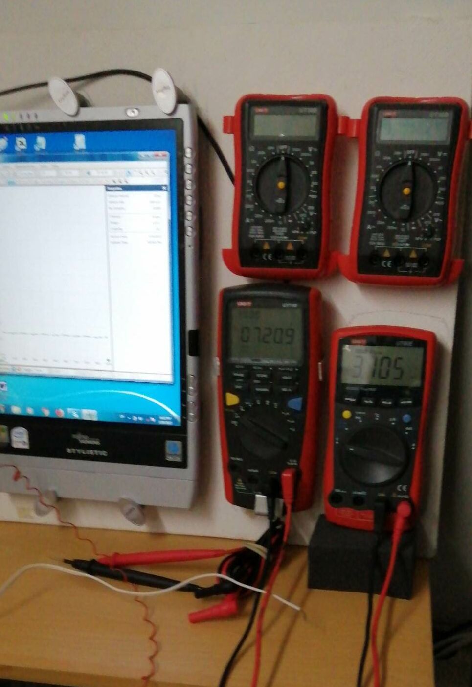
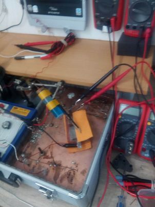
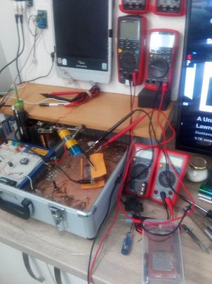
Technotoy was not set in recording mode for these two stages but the instruments were connected to help with setting up and testing the points of contact for the 'pipe-to-soil potential measurements'.
 ..
.. ..
.. ..
.. ..
..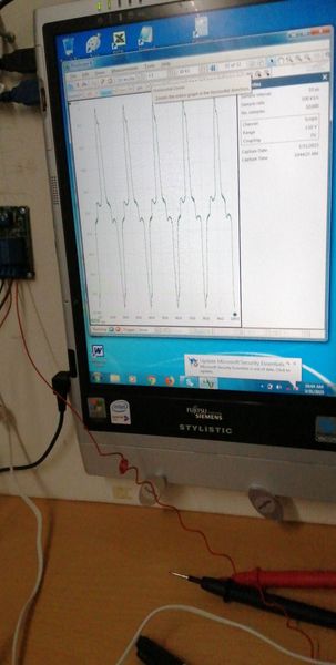
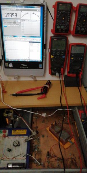
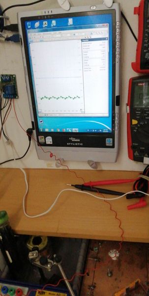
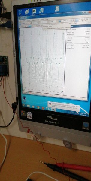
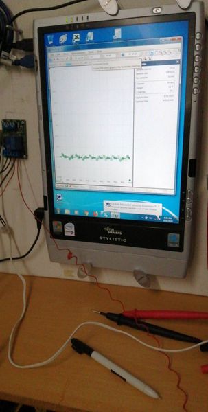
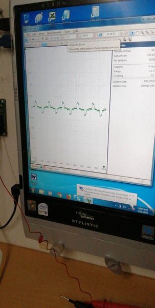
The oscilloscope is useful at this stage to show corrosion noise when connected and atmospheric electrostatic noise when not connected. I later stages it will prove that the mythical 'off potential' cannot be measured in field work and in most laboratory work. However, a timer is useful to identify individual pipelines when conducting DCVG and CIPS surveys.
 ..
.. ..
.. ..
.. ..
..
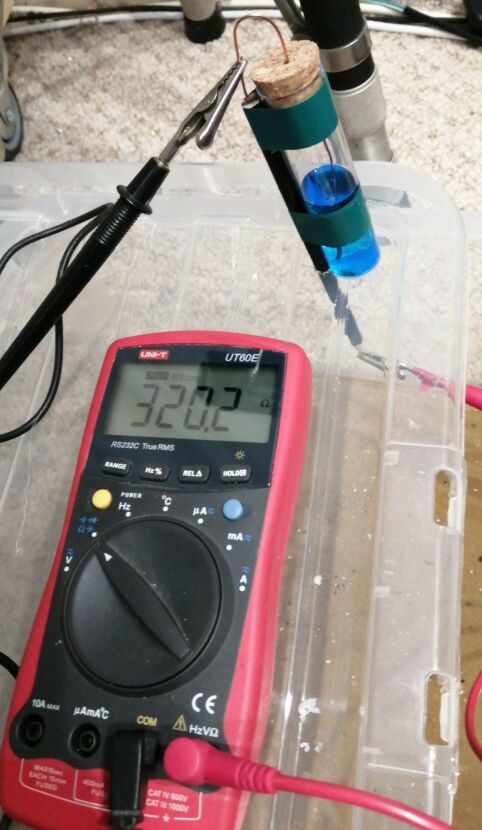
During these stages we saw how to make and use the CPN half-cell that is closer to a half-cell than those in use by other organisations.
 ..
..
I have used the term 'half -cell' because that is in common use in our industry but is totally incorrect. The Nernst equations that are quoted as the authority for it's use refers to the 'HALF CELL REACTION' and this is not an tangible obstacle it is a measurable electro-motive force. Science uses several arrangements to measure electrochemical reactions and the definitive standard is described in DIN 50918.
It has always been impossible to make this measurement in CP field work as the Luggin capillary must be close to the ANODE of the corrosion cell to avoid the IR drop in the vessel labelled 7 in the drawing. This is NOT a voltage drop, it is a potential gradient caused by the charges from the anode (number 5 'the working electrode') dispersing following the inverse square law of radiation. The fallacy that we can measure this value by switching off the CP system is ridiculous.
The CPN half-cell does not overcome this problem but has the advantage that it does not introduce copper sulphate into the ground and that the carbon (graphite) probe does not react to most soils and waters.
We will see in the next stage of this experimental demonstration that we can replicate DIN50918 in the field by using the Alexander Cell that is a corrosion cell in which I have separated the anode from the cathode.
 ..
.. ..
..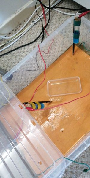
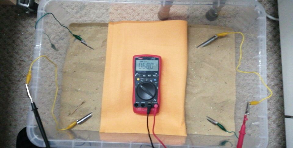
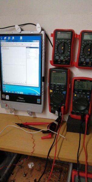
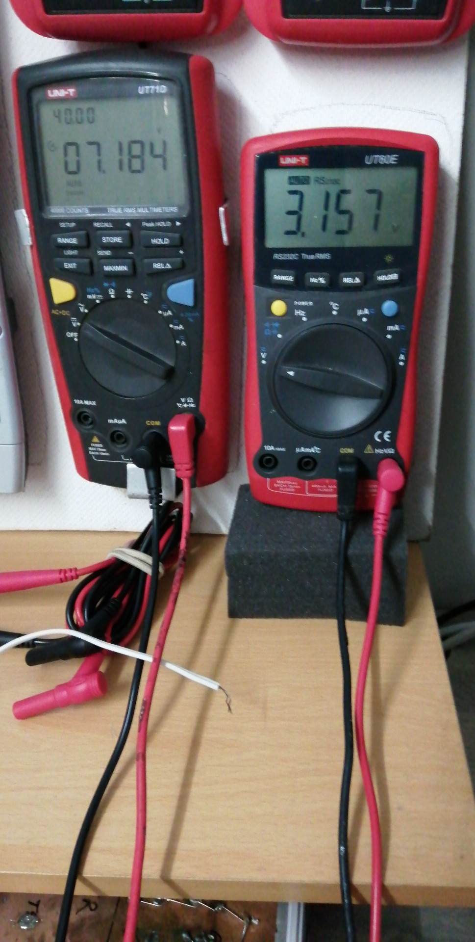
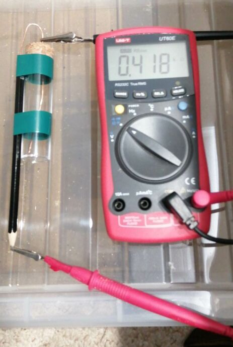
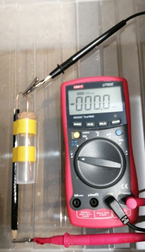
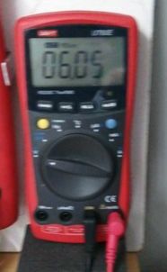
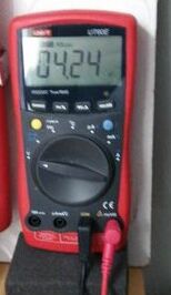
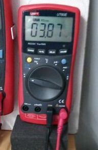
These pictures show the CPN half-cell in three different positions in the demonstration tray and the three different voltages prove that the exact point of contact with the electrolyte is crucial to the accuracy of the reading.
 ...................
 ...................
 ..
.. ....
....
These pictures show the CPN half-cell in three different positions in the demonstration tray and the three different voltages prove that the exact point of contact with the electrolyte is crucial to the accuracy of the reading.
This the reason that we cannot compute data acquired in this way but we can compute data when we use the Alexander Cell to correct the criterion. The pictures below show the Alexander Cell incorporated in Technotoy that simulates the experiment and can simulate field data to allow it to be computer analysed. This will be explained in the next stage of this experimental demonstration.
 ...........
 ..........
The analysis of this experiment, so far. proves that stray current can be physically modelled to support the notion that a moderate amount of DC energy entering and leaving a submarine pipeline can dissolve alluminium and cause hydrogen embrittlement. Less than one amp over 8 hours caused visible results that can be predicted by data acquired using the principles of DCVG and CIPS surveys, if fully understood.
